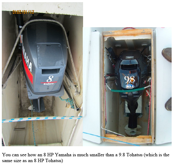
With outboards changing from 2 –stroke to 4-stroke we are faced with the problem that the new breed of engines are bigger (fatter) and heavier than the 2 strokes for which the outboard well was designed. If you cannot obtain a second hand 2 Stroke you are faced with choosing a new 4 Stroke. Having checked out as many weights and sizes as we could, we finally narrowed the choice to three engines:
Tohatsu 6hp; 8hp; 9.8hp
They are all available with 6A power output and what they call “sail drive” which just seems to be a four bladed low pitch prop.
The 6hp “saildrive” is only listed with longshaft but I am sure it can be ordered in short shaft, which is what is needed to fit the well. The 6hp weight is given as 26kg which suggests you would need to add 2kg to the engine to meet class minimum weight. But this is dry weight and since lightness is a
virtue in outboards, and advertising being what it is, it could be the motor actually weighs more than this. The 8hp and 9.8 hp weigh the same at 37kgs. They have the same engine capacity, presumably the higher output is achieved by tuning the engine.
All the other engines on offer at the time – Honda, Suzuki etc quote heavier weights, and not being able to go around the showrooms with a scale we had to work off the published data. After considering the power requirements we decided that the 6hp would not have the kick to go against a head wind and foul tide, and since the excuse to get an Impala (as opposed to a J24 or J80) was to do some family cruising we thought we better have enough power.
Since the 8hp and 9.8hp are rated at the same weight we chose the 9.8hp. True we are carrying 9kgs more weight, but this is very small beer compared to the excess weight of the helmsman, and sitting 2 inches further forward re-balances the boat. Also the 4 strokes use only half the fuel of a 2 stroke, so you tend to carry less fuel.
The 6 amp charger has keep the battery topped up for two seasons, using the radio, GPS, log, depth, and occasionally the led masthead nav light. It gets about 40 minutes charge a week going to and from the race area. The next problem was fitting it. I had taken a mass of measurements and compared them to the line drawing of the engine. The movement of lifting and tilting the engineis quite complex to draw out. I realized that the key measurement is too make sure that the overall length of the motor is less than the length of the motor well. For the rest we relied on trial end error.The original tracks were still on the boat, although they had been re-sited at least once.
The first task was to figure out where the track had to be in the motoring position. I don’t know if the skegs on modern motors are thicker than the 1970’s models, but the tolerance between right and wrong on this measurement is not much, keeping in mind that there is quite a lot of movement of the leg between neutral and full power forwards and then a large movement when going into reverse. I now know that the Tohatsu is mounted on fairly flexible internal engine bearers and even if the main
engine clamp is locked solid the engine, the skeg still moves forwards under load.
One issue is that the forward top edge of the well has a pronounced lip, and we angled the track aft at the top so the engine casing would miss this lip as the engine is pulled up.
Another variable is the correct depth of the engine – for the exhaust to work properly it must not be buried too deep, and initially we underestimated the amount by which the stern buries when under power and the crew are all huddled in the cockpit. We now have it adjusted with the cavitation plate just level with the hull. The prop will cavitate if two people go to the bows or if you are getting underway in very choppy conditions. In the first case is easy to fix, in the second, open the throttle
gently so the stern progressively settles as the power comes on. I solved all this by getting someone really strong to hold the engine in its various positions while I ran around with a marker pen trying to second guess the correct position of the tracks.
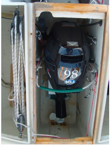
The main body of the Tohatsu has a much larger fore and aft size than an old 2 Stroke, so even with the engine bearer at the lowest position it still sticks above the deck level of the well by about 40 mm. I thought of making a blister on the hatch cover, but the amount is too great for that, and a simpler solution was to fit a wooden beading 40mm high to the top of the well and hatch just sits on that. It has worked fine for two seasons. Actually it gives the helmsman something to brace a foot against when tacking and trying to get back up on the windward rail – a task that seems to get more difficult
each season !
As mentioned above you don’t want the engine too deep I the water under way, but you do need to push the engine to the bottom of the track for stowing, so we have two hooks which fix the motoring position, and can be flipped off for stowing.
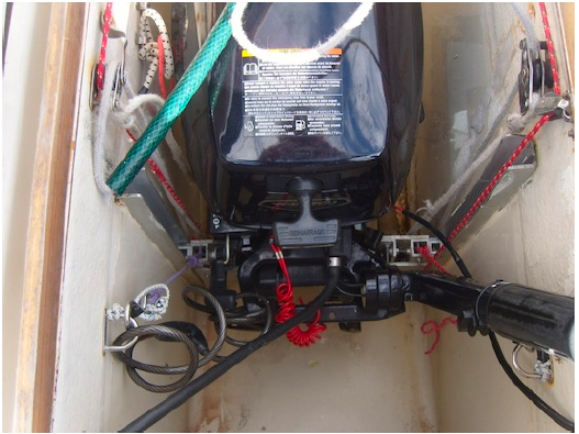
The engine bearer (what some might call a transom plate) was the next problem. For the first season we used the one inch plywood bearer which came with the boat, but as the season wore on it started to flex under load from the engine, to the point where thefront of the skeg was bearing against the hull.
I made an all aluminium bearer from two sheets of 5mm and 19mm square bar. After some trial and quite a lot of error, I ended up with slides faced with Delrin (Acetal) which with a dollop of silicone grease are a very good fit in the original one inch track. This bearer is absolutely solid, without any flexing.
The original method of fixing the track seems to have been to bolt it to the sides of the well, with some sealant. When they get loose water can pour into the two stern lockers. In addition the walls of the well are not a regular thickness, being much thicker at the top and bottom so the track, which cannot bend, does not lie flat and make a good watertight seal.
The solution I used was to shorten the track so it misses the thickened top and bottom, and add a one inch wood batten to the back (inside the lockers). Since the locker wall is quite rough the batten is bedded in foaming PU glue and the track (inside the well) is bedded in Sikaflex. I got the whole assembly ready, and we actually we took the boat out before gluing it to make sure the tracks were in the right place, then glued it up and bolted it in place all in one go. I added a couple of extra bolts in the part of the track which comes under load. The backing batten spreads the load over the whole
fiberglass wall and so far there has been no movement or leaks at all. (Unlike my previous Impala).
So now we had a motor which went up and down smoothly, did not bash the well opening, and could be closed to within an inch of the original design. There was still the problem that the engine weighs 37 kgs and even with a 2x purchase it was a problem handling the engine especially in a seaway, trying to steer, keeping out of the way of the boom and receiving a flood of gratuitous advice.
Clearly we needed something to counterbalance the weight of the engine, so that you are just lifting say 5kgs. If this was a lifting bridge or the lift (elevator) in a building you incorporate a ounterbalance in the design so gravity does most of the work.
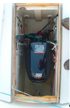
Clearly adding another 30kgs to the back of the boat is not a good idea, so I decided to try a spring loaded method. After some messing about I found that a good length of 12mm shock cord would do it. You need a similar pull at the top of the track as at the bottom, so the cord needs to be long. A short length might help out initially, but would come slack as the engine came to the top of the track. To get the distance I have run the cord through a series of pulleys in the locker, with the business end
connected to a pair of lines which go through the locker wall and lead down to the engine bearer in a mirror image to the line we use to pull the engine up. The picture shows it’s really quite straightforward.
As a result the engine is quite light to use, and actually we need to push it down ! The friction in the track tends to keep the engine wherever you leave it, which is a big help when tilting the engine.
The final piece of the jigsaw is the aft edge of the well opening. Invariably this has been attacked by the thin knife like fins you get on the bottom of outboard motors. I have theorised about building in a steel plate, or a piece of teak. In the end the method that seems to work is a very liberal amount of the green glass filled Plastic Padding – the key to success is to cover a really big area on the inside of the hull. This material sets really hard but needs a decent surface area to get a good grip on the hull. It will still need repairing, but less often.
One day I plan to find how much of that fin we can cut off without going into the gearbox.
I won’t bore you with all the measurements, but if someone is fitting a Tohatsu let me know and I’ll take them off the boat.
A big thank you to Mike Burrell for the Yamaha photos.
2 Comments
Chris P. · March 17, 2018 at 10:47 pm
Hello Kevin!
This is a great article!
I am just planning to replace my engine to the sameish type of tohatsu. Is that possible, that you can maybe send me the details about the rail length and position in the well, and the rail shape, and the engine holder/barier details.
My impala has no rails in the well, and at the moment I have a longshaft yamaha installed, which I would like to replace to a short shaft because of racing. So I have to create the rails from scratch as well. I would be really good to have some advice as well.
Thanks and regards,
Chris
Kevin Palfreeman · December 15, 2025 at 3:54 pm
Dear Chris,
Really sorry not to have seen your original message of 7 years ago !!! I was just thinking of writing some notes on our electric start Selva 6HP and was checking what I wrote about the 8HP so saw your message. (We are often late at the start )
How did you get on with the installation ?